Recently, through influence of friends and a bit of chance, I’ve become interested in the dance game Pump it Up (PIU). For those who don’t know what it is, PIU (owned by Andamiro) is essentially a Korean version of Konami’s Dance Dance Revolution, with arrows in the corners and middle instead of the cardinal directions. You’ll likely find machines for the game at local arcades, with several big names (i.e. D&B) supporting the brand as well.
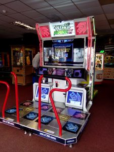
A Pump it Up: Prime 2 machine (most recent iteration).
As the closest machine is 45 minutes away from where I’m staying at Virginia Tech next year (and honestly 30 minutes away from my house in Atlanta on a good day), I decided to try my hand at building my own dance pad to hook up with a computer and play with StepF2, a mod for Stepmania that emulates a version of PIU. Plus, the market for professionally made pads is somewhat barren, meaning I’d have to wait for quite a bit and spend a small fortune if I wanted to buy a decent pad instead of building my own. Decent pads can be anywhere from $300-500 depending on manufacturer. I was able to build mine for about $175-200, saving a fair bit of money.
First came deciding on what materials I wanted to use for the build. I wanted this to be fairly lightweight to ease portability (mainly from home to school) but also look decent. Eventually I just settled on 1/2″ plywood for base/support and 1/4″ birch sheets to use for the pads and pad platforms. I tried to stay as true to the original dimensions of the pad as possible, which resulted in overall dimensions of 35″x35″x1″ (which just barely fits in the trunk of my 2006 Prius, let me just add). To add a layer of protection (for both the wood and the feet of those who are playing), the top is covered in a layer of 1/32″ polycarbonate plastic. Other than that, I ended up using an 8mm (just over 1/4″) high density foam to act as a spring for the pad (mechanism will be explained later) and some Cat5 to wire everything up. An Arduino Leonardo was used as the computer (chosen over other options due to its ability to be plugged into a computer and function as a keyboard).
First came building the frame. The entirety of the pad is rested on a sheet of 35″x35″x1/2″ plywood acting as a base, with 1″ strips of 1/2″ plywood going around the sides of the base to act as a frame. Again, 1/2″ plywood was used as spacers between the pads which resulted in a sort of frame for each pad.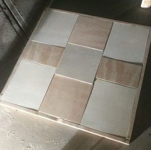 The completed frame.
Next came designing the mechanism for the pressure sensors to determine when the pad is pressed. The mechanism is simple and rather easy to understand. Essentially, underneath each 1/4″ pad is a 1/4″ platform with a sheet of interlocking foil on it acting as a conductor (2 separate halves). One of these halves is connected to power and the other is connected to a corresponding pin on the Arduino. Underneath the pad itself is a single strip of aluminum. When the pad is pressed, the strip underneath the pad itself connects the two halves of aluminum sheet, completing the circuit and causing a change of state for the pin on the Arduino. High density foam was laid around the platform (there is an inch space between the platform and 1/2″ support piece) and functioned as a sort of spring mechanism to keep the pad above the sheet in its natural state. Cat 5 was used to wire everything together, with heavy duty staples being used to fasten it in place with the aluminum and hot glue elsewhere.
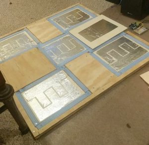
The sensor mechanism of each pad. You can see the interlocking pattern of aluminum present. A single pad is shown at the top of the pad to demonstrate what the connecting sheet looks like.
The software side of this project is incredibly simple. Each of the 5 pads is assigned a pin on the Arduino Leonardo and whenever a change in state is observed, a signal is sent to the connected keyboard that signifies either a key press or release on a keyboard. This mapping is then mirrored on StepF2’s key settings to complete the setup. If you want to see this code for yourself or want any tips/pointers, feel free to email me.
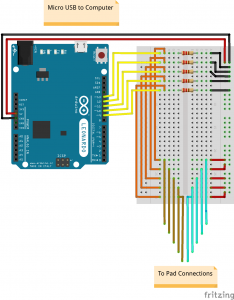 The Arduino circuit for this build. It’s set up in such a way that the pins read low when the pad is not engaged and high when engaged.
For the finish, I coated the frame and top half of the pads in a layer of black spray paint. I traced a set of PIU arrows I found online, sized them correctly, and had them professionally printed and laminated. On top of the frame is the 1/32″ layer of polycarbonate mentioned earlier, of which was easy to work with and functions just fine. The added layer of polycarbonate keeps the pads themselves from wiggling too much, a problem that was present in an earlier stage of the build (another work around for this would be to glue the pads to the foam, but I like the idea of being able to take the pad off in case one of the sensors becomes unresponsive or some other error occurs). I’m incredibly pleased with the final look and feel of the pad overall.
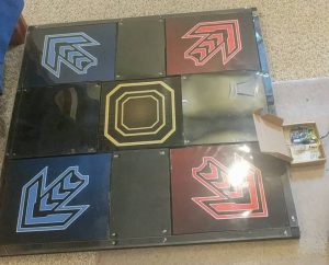 The final version of the pad. You can see the Arduino hooked up at the top of the pad. As of right now, I’m just using a cardboard box to house everything
This was an incredibly fun way to spend about a week of my time and I’m definitely satisfied with the result. I still have some tinkering around with the sensitivity of the sensors, but that’s a gradual process that doesn’t require too much effort on my end. The pad works and plays as expected. As for things I would change if I were to do this build again, I would have rather used a CNC laser cutter instead of a table saw to do all the cutting, as I found out quickly that even with double and triple checked measurements, some cuts are just bound to be inaccurate (especially for someone like me who isn’t too familiar with carpentry or work like this in general). Luckily, it didn’t turn out to be that big of an issue. Other than that, I think I should have used a roller/more traditional paint instead of spray paint, as it was hard to keep the layers even across the entirety of the 35″x35″ pad.
Thanks for reading! If you have any questions or comments, feel free to email me at [email protected].
Recent Comments